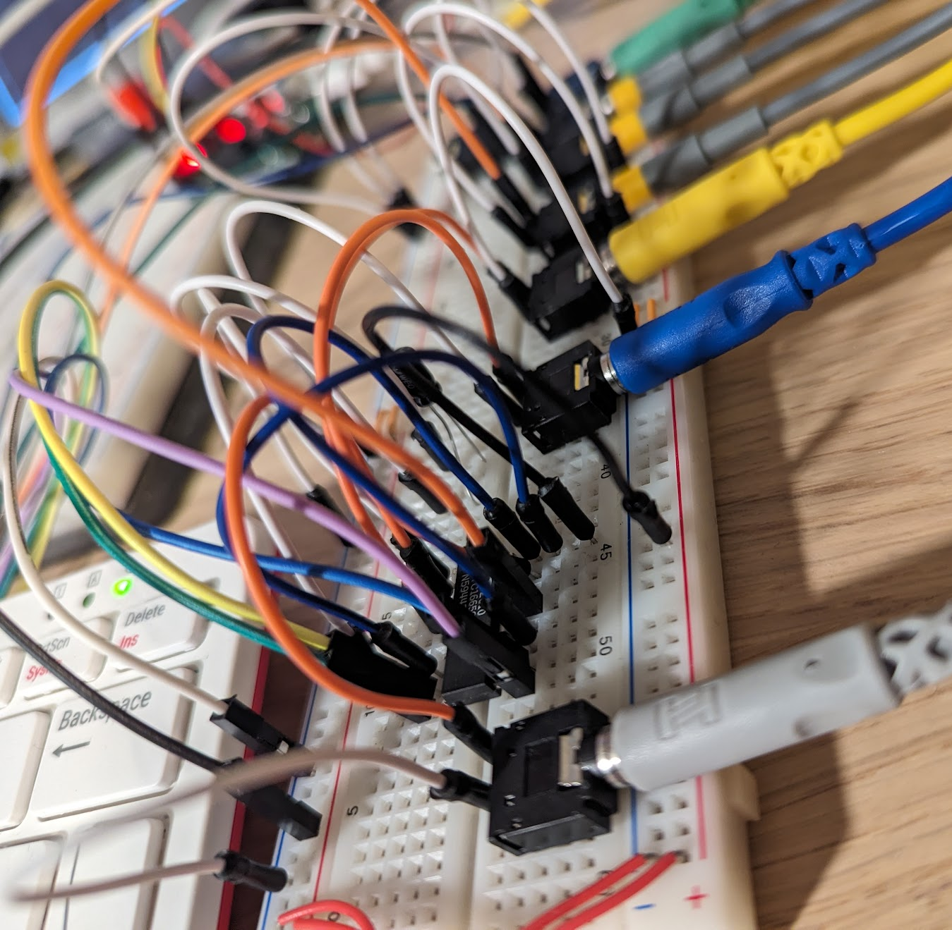
2024-03-03 - we're back, baby
so yeah i kinda dropped this for the last...year. whatever. life and other interests happen. anyway, i've been back at this project in recent weeks and then i remembered i created this project blog. so here's an update!
not long after the last blog post, i made an error that probably contributed to me putting the project down for a long while. i was playing with the pwm to voltage converters i was talking about in that last post, and i hooked something up wrong. i didn't notice for a while. i wasn't getting the expected outputs...or much output at all really. then i smelled hot electronics...yeah. i'd fried the converter thoroughly and the hookup was so incredibly wrong i couldn't stand looking at it all for a bit.
anyway. silver linings. the pwm approach was kinda stupid anyway. a much better approach is a dac controlled over spi or i2c. so now i've picked up some ltc1665 8 channel 8 bit dacs. mostly got 2 in case i blow up one. which almost happened because i'm kind of an idiot.
this was my first experience with spi and that added an extra layer of "am i doing this right? like at all?" to the whole affair. i am awful at bitwise operations and indeed i made at least one big mistake along the way to having the correctly configured 12 bit commands the dac needed from me. and that got me to a really frustrating point because sometimes everything would work absolutely beautifully...for like 30 seconds at a time. and i'd have to disconnect/reconnect half the damn breadboard before i'd see life again. i tried different power supplies. i tried making the chip power and reference voltage totally independent. i did a lot of things but i still had basically the same problem.
then - shocker - i read the manual. the purpose of each of the dac's pin was clear from the pinout in the datasheet. i hadn't really spent much time looking at the typical installation circuit diagram, and i realized there were two things in that that weren't in mine...oops.
first thing, and probably the one that matters most - they had a 10µF capacitor hanging off the reference voltage pin, connecting it to ground. in retrospect, some connection to ground for the reference voltage makes sense...it can be a different supply than the chip power and it should have a path to an appropriate ground. and the capacitor makes sense for filtering out noise, you don't want other stuff on the same ground rail to affect the reference voltage and thus all the dac outputs. so i added a capacitor.
the other thing was connecting the chip power to the clr (clear) pin, the one that can be used to reset all outputs to their default state. i'd tried that with nothing connected and connected to ground because i'm used to reset pins on other chips behaving as if reset never happens when i do that. go figure. anyway, connected the clr pin to the chip power just to be safe.
so now i can finally start doing fancy things, because i have 8 variable voltage outputs and i can pair those with gpio pins to simulate the tone and keypress signals of a synthesizer keyboard. and i have one hell of a messy breadboard. need to think on how i want to mount some of this stuff on to a prototyping board.

back to blog index
back to jattdb.com
